
Recently I’ve built a cool new Corne keyboard, and I’d like to share the build process with you guys!
Components:
This build was a bit of experimental. I didn’t want to solder switches as I wanted to try a few different types. And ProMicro – I decided to make it socketed so I could change the controller if I need to.
- PCBs were bought from keyhive.xyz
- Acrylic plates were laser cut through https://www.ponoko.com
- Elite-C
- OLEDs
- Zealios V2
- SMD diodes
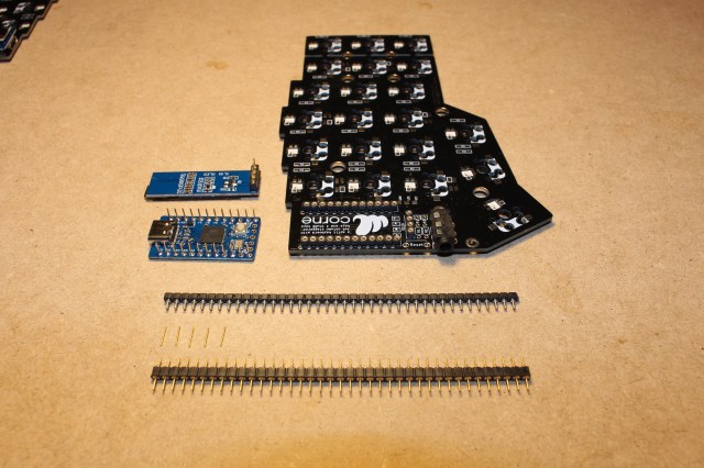
- 64-pos Mill-Max socket row. Used for Elite-C and OLED display socketing. One row is enough for the build.
- Mill-Max pins. Will be soldered to Elite-C. You need 48 (12×4) but get some extra just in case.
- 64-pos Mill-Max connector. This two-sided connector will be soldered to OLED displays. I used 64 pos but only 8 (4×2) pos are needed for OLEDs. You can get something like this instead.
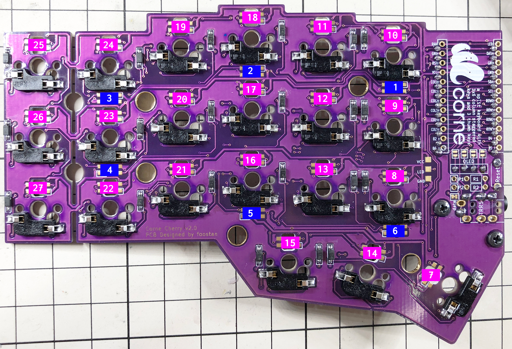
Build
The original build guide was created by foostan, and that was the source that I used.
I’d like to highlight the socketing part only, as all other steps are the same as in the original build guide.
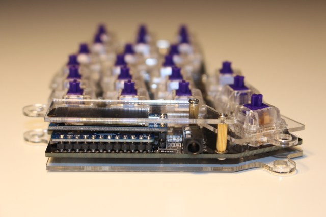
Socketing ProMicro/Elite-C
I decided to use Mill-Max low-profile sockets for ProMicro. I’d need one 48-pos row cut by 4 parts to get 4×12-pos rows for two ProMicros. But it’s always a good idea to get some extra just in case, so I ordered the 64-pos row on DigiKey.
The ProMicro doesn’t have any pins pre-soldered out of the box, so we also need 48 Mill-Max pins for it.
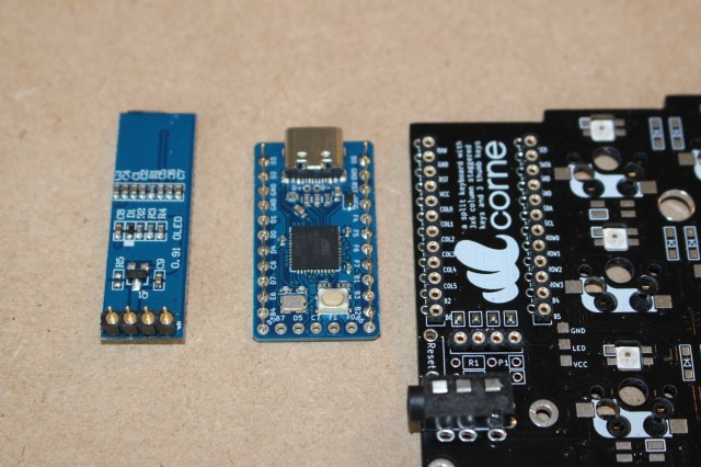
Here is the photo with the socket row, pins, and ProMicro/Elite-C:

Socketing OLEDs
First option
The OLEDs come with the already pre-soldered standard connector. That one is not compatible with Mill-Max sockets.
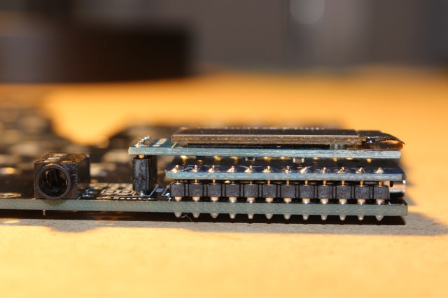
The easiest way to attach OLEDs with the standard connector is just to get these sockets and solder them in place. Sockets are shown on the picture above – between TRRS connector and Elite-C.
That would work just fine, but OLED height will be a bit bigger than I’d want to. So I didn’t use this approach.
Second option. Low-profile
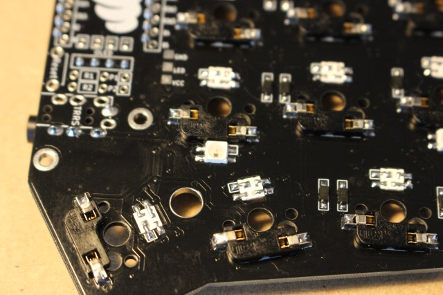
The second option is to desolder OLED pins and solder this Mill-Max 2-sided connector instead. And then use the same sockets that we’ve used for the ProMicro/Elite-C:
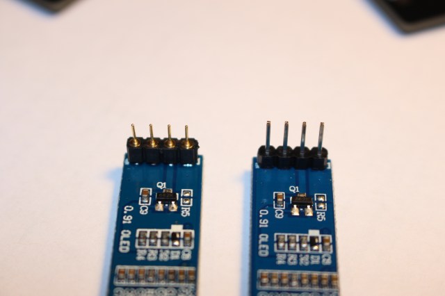
The Mill-Max 2-sided connector on the left and the original on the right.
All sockets, pins, and connectors are soldered.
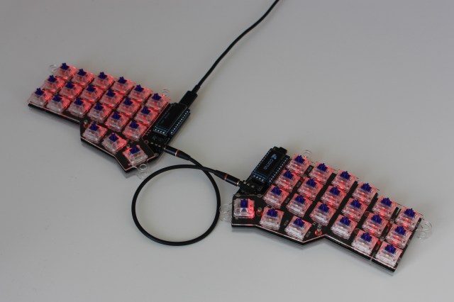
Soldering LEDs
Make sure you set the soldering iron temperature to ~420F -430F. LEDs are too heat sensitive!
Start soldering the first LED from the original build guide image. And test it. It should light up (make sure you flash the ProMicro first!)
All LEDs are chained so if the very first (facing down) is broken you won’t see other light up. If the very first one lights up, solder the second one and test again. If the second doesn’t work you have to check two places – output from the first LED and all joints on the second. The same for every following LED.
Adding switches and final look
I used Zealios V2 switches for the build. I’m looking for a good tactile non-clicky switch and hope these will work fine!
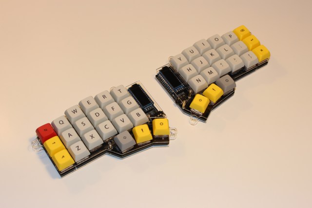
Hope this helps if you just starting the Corne build!
If you have any ideas on how to improve the process, please let me know in the comments!
Thanks!

Pingback: Trackpad in a Keycap For Corne/CrKbd | Volodymyr Lukashevych
Pingback: Trackpad in a Keycap for Corne/CrKbd Keyboard | Volodymyr Lukashevych
Thanks for this blog post and the video! I’m following your lead doing my build. 👍
LikeLike
Hey, thanks! Happy to hear you’ve found it useful!
LikeLike
I just wanted to let you know that this helped me out so much. Just knowing where I can get stuff laser cut or what Mill-Max sockets to use and where to buy them is information that would have taken forever for me to find on my own. And then obviously the build video itself is extremely helpful. Just wanted to pop in to say thanks!
LikeLike
The acrilic plates with tenting are not online on github anymore. Do you have them? Thank you.
LikeLike
https://github.com/foostan/crkbd/tree/master/plates/tilting-tenting
LikeLike
How much for a built one?
LikeLike